
Piping and Instrumentation Diagrams (P&ID) are detailed graphical representations of process systems, showcasing the interconnection of equipment, piping, and instrumentation. They play a crucial role in planning, operating, and maintaining industrial processes, ensuring safety and efficiency. P&ID symbols, standardized for clarity, are essential for communication among engineers, technicians, and operators, forming the backbone of process documentation.
1.1 Definition and Purpose of P&ID
A Piping and Instrumentation Diagram (P&ID) is a detailed graphical representation of a process system, illustrating the interconnections of equipment, piping, and instrumentation. It serves as a critical tool for planning, operating, and maintaining industrial processes. The primary purpose of a P&ID is to provide a clear visual representation of the system, enabling effective communication among engineers, technicians, and operators. It outlines the flow of materials, energy, and signals, ensuring process safety, efficiency, and compliance with standards. By standardizing symbols and layouts, P&ID ensures consistency and clarity, making it an essential document in the design and operation of process industries.
1.2 Importance of P&ID in Process Industries
P&IDs are indispensable in process industries for their role in ensuring operational efficiency and safety. They provide a comprehensive view of process systems, enabling engineers to identify potential hazards and optimize designs. By standardizing symbols, P&IDs facilitate clear communication among stakeholders, reducing errors and enhancing collaboration. They are essential for training personnel, troubleshooting, and compliance with industry standards. Regular updates to P&IDs ensure that modifications are accurately reflected, maintaining system integrity. Their importance extends to project planning, where they serve as a baseline for construction and commissioning, ensuring smooth operations from design to execution.

Standard P&ID Symbols
Standard P&ID symbols represent equipment, valves, instruments, and connections in process systems. These symbols, standardized by ISA S5.1, ensure consistency and clarity across industries, aiding in accurate interpretation.
2.1 Common Symbols Used in P&ID
Common P&ID symbols include representations for valves, pumps, instruments, and piping components. Valves are depicted with standardized shapes, such as gate, globe, and control valves. Instrument symbols vary by function, like pressure gauges, flowmeters, and level indicators. Equipment symbols, including pumps, compressors, and heat exchangers, are also essential. These symbols, often detailed in PDF resources, ensure uniform understanding across industries. They are crucial for visualizing process flows, enabling effective communication among engineers and operators. Proper use of these symbols adheres to standards like ISA S5.1, ensuring clarity and consistency in P&ID documentation.
2.2 Valve Symbols and Their Variations
Valve symbols in P&ID represent various types and functions, such as isolation, control, and safety valves. Gate valves are shown as simple rectangles, while globe valves include a bulb shape. Ball and butterfly valves are depicted with circular and diamond-shaped symbols, respectively. Check valves have arrows indicating flow direction. Control valves often include actuator symbols, like circles or squares, showing their operation. Safety valves, like pressure relief valves, are marked with specific notations. These variations ensure precise representation of valve functions in process diagrams, aiding in accurate system design and operation. Standardized symbols, detailed in PDF guides, enhance consistency and readability across industries.

2.3 Instrumentation Symbols
Instrumentation symbols are essential for representing measurement and control devices in P&ID. These symbols denote elements like pressure switches, temperature transmitters, flow meters, and level indicators. Standardized symbols, such as those from ISA S5.1, ensure consistency across diagrams. For example, a pressure indicator is shown as a circle with a “P,” while a flow meter is represented by a diamond with an arrow. Control valves are depicted with actuator symbols, indicating their operation. Safety devices, like pressure relief valves, have distinct notations. These symbols are detailed in PDF guides, ensuring clarity and uniformity in process documentation. They enable engineers and operators to interpret system functions accurately, facilitating efficient design and operation. Proper use of instrumentation symbols is critical for maintaining process safety and efficiency.
2.4 Actuator Symbols
Actuator symbols are crucial in P&ID for representing devices that control valve operations. These symbols indicate how valves are actuated, whether pneumatically, electrically, or hydraulically. For instance, a circle with a diagonal line denotes a pneumatic actuator, while a rectangle with an “E” signifies an electric actuator. These symbols are combined with valve representations to show their operation type. Standardization ensures clarity, with resources like ISA S5.1 guiding their use. Actuator symbols also specify control actions, such as fail-safe or modulating operations. Their inclusion in P&ID is vital for understanding system automation and integration with control systems. PDF guides and legend sheets often detail these symbols for easy reference, ensuring consistency across designs and operations.
Instrumentation Symbols in Detail
Instrumentation symbols provide detailed representations of measurement and control devices. They are standardized for clarity and consistency, ensuring precise communication in process diagrams. Essential for accuracy and efficiency.
3.1 Pressure-Related Symbols
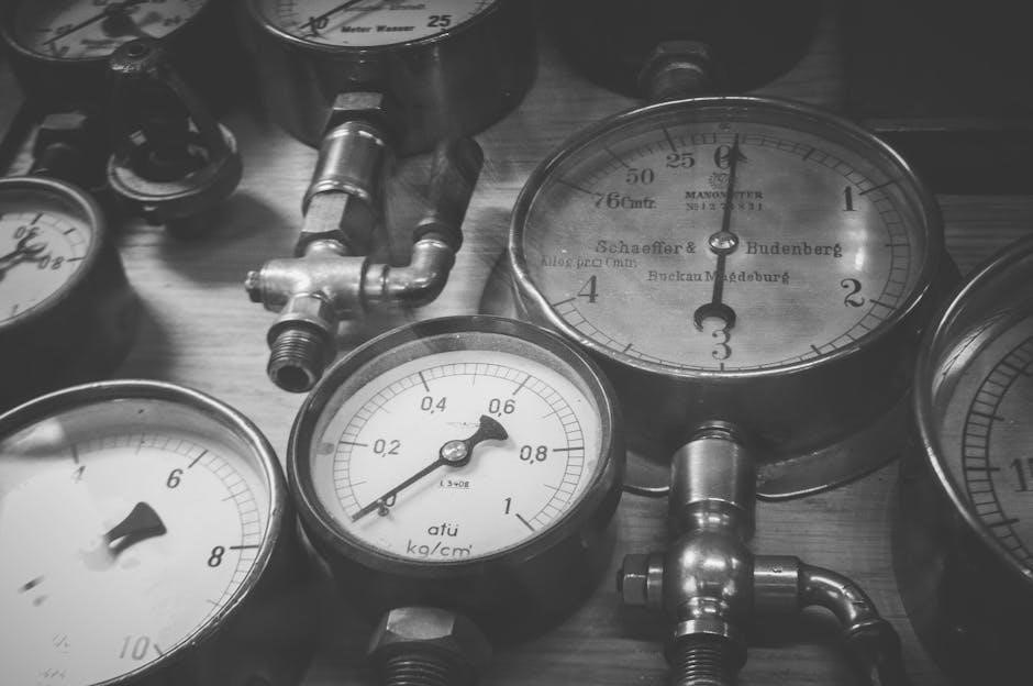
Pressure-related symbols are fundamental in P&ID diagrams for indicating pressure measurement and control. Common symbols include pressure indicators, transmitters, switches, and controllers. These elements are crucial for monitoring and regulating pressure levels in process systems, ensuring safety and efficiency. The symbols are standardized according to ISA S5.1, providing clear visual representation. For example, a pressure indicator is depicted with a dial-like shape, while a pressure transmitter uses a triangular or rectangular shape with lines indicating connections. These symbols are essential for identifying pressure safety valves and other critical components in process control loops. Their accurate representation ensures effective system operation and maintenance.
3.2 Flow Measurement Symbols
Flow measurement symbols are essential in P&ID diagrams for monitoring and controlling fluid flow rates. Common symbols include flow indicators, transmitters, totalizers, and switches. These elements are standardized according to ISA S5.1, ensuring clarity and consistency. Flow indicators are often represented by a rectangular shape with an arrow indicating flow direction, while transmitters use a triangular or circular shape. Differential pressure transmitters for flow measurement are depicted with two lines connected to a triangular symbol. These symbols are vital for identifying flowmeters, orifice plates, and other devices in process systems. Their accurate representation ensures precise flow rate monitoring, which is critical for process optimization and safety.
3.3 Level and Temperature Symbols
Level and temperature symbols are critical in P&ID diagrams for monitoring and controlling process conditions. Level symbols include indicators, transmitters, and switches, often represented by rectangular shapes with internal details. Temperature symbols incorporate thermometers, thermocouples, and thermal elements, typically shown as circular or triangular shapes. These symbols are standardized according to ISA S5.1, ensuring uniformity. Level indicators may feature a vertical bar with gradations, while temperature transmitters are often depicted with a diagonal line inside a circle. These elements are vital for maintaining process stability and safety, enabling precise measurement and control of fluid levels and thermal conditions in industrial systems.
3.4 Control and Safety Symbols
Control and safety symbols are essential for representing devices that regulate and protect process systems. These symbols include controllers, switches, alarms, and safety interlocks. Control symbols, such as pressure controllers and flow regulators, are often depicted with circles or rectangles containing specific notations. Safety symbols, like emergency shutdown (ESD) valves and fire alarms, are designed to stand out for quick identification. These symbols are standardized to ensure clarity and consistency, adhering to ISA S5.1 guidelines. They play a critical role in maintaining process stability, preventing hazards, and enabling rapid response to emergencies. Proper use of these symbols ensures safe and efficient system operation, making them indispensable in P&ID documentation.

P&ID Legend Sheets
P&ID legend sheets are comprehensive resources that define and explain the symbols, abbreviations, and notations used in P&ID diagrams, ensuring clarity and consistency in interpretation.
4.1 Legend Sheet as a PDF Resource
A legend sheet in PDF format serves as a vital reference document, providing standardized symbols, abbreviations, and notations for P&ID diagrams. It ensures consistency across projects and teams, making it easier for engineers and technicians to interpret diagrams accurately. The PDF format allows for easy sharing and accessibility, ensuring that all stakeholders have access to the same set of guidelines. This resource is particularly useful for training new personnel and maintaining uniformity in documentation. By standardizing symbols, it reduces errors and enhances collaboration, making it an indispensable tool in the process industries.
4.2 Importance of Legend Sheets in P&ID
Legend sheets are indispensable in P&ID as they provide a unified reference for understanding symbols, abbreviations, and notations. They ensure clarity and consistency across all diagrams, preventing misinterpretations that could lead to operational errors. By standardizing symbols, legend sheets enhance communication among engineers, technicians, and stakeholders, fostering collaboration and efficiency. They also serve as a training tool for new personnel, helping them grasp the terminology and conventions quickly. Additionally, legend sheets support compliance with industry standards, ensuring that documentation meets regulatory requirements. Their importance lies in maintaining accuracy, reducing ambiguity, and streamlining the design and operational processes in the process industries.

Development and Standards
The development of P&ID standards, such as ISA S5.1, ensures consistent symbol usage across industries, enhancing clarity and safety in process documentation and design.
5.1 ISA S5.1 Instrumentation Symbol Standard
The ISA S5.1 standard provides a comprehensive set of symbols for instrumentation and control systems, ensuring uniformity in P&ID creation. It defines graphical representations for devices like valves, sensors, and actuators, facilitating clear communication among engineers and technicians. By standardizing symbols, ISA S5.1 enhances the readability and consistency of diagrams, which is critical for process safety and efficiency. This standard is widely adopted across industries, including oil, gas, and chemical processing, making it a cornerstone of P&ID development. Adherence to ISA S5.1 ensures that diagrams are accurate, scalable, and compatible with international engineering practices.
5.2 Evolution of P&ID Symbol Standards
The evolution of P&ID symbol standards reflects advancements in technology and industry requirements. Early P&ID symbols varied widely, leading to confusion and inefficiency. The development of standardized symbols, such as those in ISA S5.1, brought consistency and clarity to process documentation. Over time, these standards have been refined to accommodate new equipment and methodologies, ensuring diagrams remain relevant and accurate. The rise of digital tools has further enhanced symbol standardization, enabling easier creation and sharing of P&ID resources, including PDF guides. This evolution has significantly improved the effectiveness of P&ID in communicating complex process information, fostering collaboration across industries and ensuring operational safety.

Components of P&ID
P&ID diagrams include detailed representations of equipment, valves, piping, and instrumentation, ensuring clear visualization of process systems. These components are essential for accurate process documentation and analysis.
6.1 Pumps and Compressors
Pumps and compressors are critical components in P&ID diagrams, represented by specific symbols. Pumps are depicted with distinct shapes indicating their type, such as centrifugal or positive displacement. Compressors, including centrifugal and rotary types, are also illustrated with unique symbols to denote their function and integration into the process flow. These symbols are standardized to ensure clarity and consistency across diagrams, aiding engineers in understanding system operations and maintenance requirements. Proper representation of pumps and compressors in P&ID is vital for accurate process control and safety, ensuring efficient system design and troubleshooting.
6.2 Heat Exchangers and Mixers
Heat exchangers and mixers are essential components in P&ID diagrams, represented by specific symbols. Heat exchangers, such as shell-and-tube or plate-type, are depicted with unique symbols to illustrate fluid flow and heat transfer. Mixers, including static or agitated types, are shown with symbols that indicate material blending. These components are vital for process control, ensuring efficient heat transfer and proper mixing. Their accurate representation in P&ID diagrams is crucial for system design, operation, and maintenance. Standardized symbols for heat exchangers and mixers enhance clarity, enabling engineers to understand process interactions and troubleshoot effectively. Proper documentation of these elements ensures safe and efficient plant operations;
6.3 Crushers and Silencers
Crushers and silencers are critical components in P&ID diagrams, represented by distinct symbols. Crushers, such as jaw or cone types, are depicted to indicate material size reduction processes. Silencers, including reactive or absorptive types, are shown to denote noise reduction in piping systems. These components are essential for maintaining process efficiency and safety. Their accurate representation in P&ID diagrams ensures proper system design and operation. Standardized symbols for crushers and silencers enhance clarity, allowing engineers to identify their roles in material handling and noise control. Proper documentation of these elements is vital for troubleshooting and maintaining plant productivity and environmental compliance.

Reading and Interpreting P&ID
Reading and interpreting P&ID involves understanding symbols, flow paths, and system interactions. It requires knowledge of instrumentation, valves, and equipment connections to ensure accurate process control and safety.
7.1 Identifying Components on a P&ID
Identifying components on a P&ID involves recognizing symbols for equipment, valves, instruments, and piping. Each symbol represents a specific item, such as pumps, heat exchangers, or control valves. Standardized shapes and annotations guide identification, ensuring clarity. For instance, circular symbols typically denote instruments, while rectangular shapes represent controllers. Valves are often shown with lines indicating their actuation types. By referring to legend sheets or PDF guides, users can accurately interpret symbols, enabling effective system understanding and maintenance. This step is critical for troubleshooting, operational planning, and ensuring process safety.
7.2 Determining Flow Paths
Determining flow paths on a P&ID involves tracing the piping lines and identifying how materials move through the system. By analyzing the connections between equipment and valves, operators can map the flow of fluids. Symbols for valves, such as gate, globe, or check valves, indicate where flow can be controlled or restricted. Instrumentation symbols, like flow meters, further clarify the direction and measurement of flow. Actuators and control signals may also influence flow paths. Referencing legend sheets or PDF guides ensures accurate interpretation of symbols, enabling operators to understand how materials progress through the system and identify potential bottlenecks or safety risks.
7.3 Understanding Valve Lineups
Understanding valve lineups is critical for interpreting P&ID diagrams, as valves regulate fluid flow in process systems. Valve symbols, such as gate, globe, check, and ball valves, indicate their function and operation. Lineups are typically arranged to show the sequence of valves controlling flow through a piping system. By analyzing these configurations, operators can identify isolation points, control mechanisms, and safety shutdowns. Referencing legend sheets or PDF guides ensures accurate identification of valve types and their roles. This understanding is essential for maintaining process integrity, ensuring safety, and facilitating efficient system operation and maintenance. Proper valve lineup interpretation prevents errors and enhances overall process control.

Best Practices for Creating P&ID Symbols
Best practices for creating P&ID symbols include standardization, clarity, and consistency. Use approved symbols from legend sheets or PDF guides to ensure uniformity and accuracy in documentation.
8.1 Standardization of Symbols
Standardization of P&ID symbols ensures consistency and clarity across all diagrams. Using universally recognized symbols, as defined by standards like ISA S5.1, minimizes confusion and enhances readability. Standardized symbols also facilitate easier communication among engineers, technicians, and operators. Legend sheets and PDF guides provide a reference for approved symbols, ensuring uniformity in documentation. Adhering to these standards reduces errors and improves safety in process industries. Regular audits and updates to symbol libraries help maintain compliance with evolving industry practices. Proper standardization is essential for creating accurate and reliable P&ID diagrams, which are critical for process design, operation, and maintenance.
8.2 Clarity and Consistency in Layout
Clarity and consistency in P&ID layout are essential for effective communication. A well-organized diagram ensures that all components, such as valves, instruments, and piping, are logically arranged and easily identifiable. Using a consistent grid system and alignment helps maintain readability. Standardized spacing between symbols and lines prevents overcrowding, reducing the risk of misinterpretation. Consistent use of colors, line styles, and annotations further enhances clarity. Adhering to these practices ensures that diagrams are universally understood, minimizing errors in process design and operation. Tools like EdrawMax and PDF guides provide templates to achieve this consistency, ensuring P&ID diagrams are clear, accurate, and reliable for all stakeholders.
8.3 Auditing for Completeness
Auditing for completeness ensures that all necessary components and details are included in P&ID diagrams. This step involves verifying that every symbol, line, and annotation accurately represents the process system. Tools like PDF guides and software such as EdrawMax assist in cross-checking symbols against standards, ensuring no elements are missing or misrepresented. Regular audits help identify inconsistencies, such as unlabelled lines or undefined symbols, which could lead to operational errors. By systematically reviewing each aspect of the diagram, engineers can ensure compliance with standards like ISA S5.1, maintaining accuracy and reliability. A thorough audit is crucial for preventing oversights that could compromise process safety and efficiency.

Tools and Resources
Software like AutoCAD and EdrawMax aids in creating P&ID symbols, while PDF guides provide reference materials. Online platforms offer tutorials and resources for mastering P&ID design.
9.1 Software for Creating P&ID Symbols
Software tools like AutoCAD, SmartPlant P&ID, and EdrawMax are widely used for creating P&ID symbols. These programs offer libraries of standardized shapes and symbols, ensuring consistency. They allow users to design, edit, and annotate diagrams efficiently; Some software supports collaboration, enabling teams to work together in real-time. Features include drag-and-drop functionality, customization options, and integration with other engineering tools. These applications help maintain accuracy and compliance with industry standards like ISA S5.1. They are essential for professionals in process industries, facilitating the creation of clear and precise P&ID documentation.
9.2 PDF Guides and Reference Materials
PDF guides and reference materials are invaluable resources for understanding piping and instrumentation symbols. These documents provide comprehensive libraries of standardized symbols, including valves, instruments, and equipment. They often include detailed explanations of each symbol’s meaning and application. Many PDF guides align with industry standards like ISA S5.1, ensuring consistency. They are widely used by engineers, technicians, and students for training and reference. Some popular PDF resources include legend sheets and diagrams from reputable sources like SunCam and ISA. These materials are essential for accurate P&ID interpretation and creation, serving as a foundation for process documentation and design.
9.3 Online Platforms for P&ID Learning
Online platforms offer extensive resources for learning piping and instrumentation symbols, providing access to PDF guides, tutorials, and interactive tools. Websites like EdrawMax and Wondershare EdrawMax provide comprehensive libraries of P&ID symbols and diagrams, enabling users to create and customize their own designs; SunCam and other educational platforms offer courses and downloadable PDF materials, including legend sheets and reference guides. These platforms cater to both beginners and professionals, offering remote learning opportunities. They often include interactive tutorials and practical exercises to enhance understanding. Such resources are indispensable for mastering P&ID symbol standards and applying them in real-world projects, ensuring accuracy and compliance with industry norms.
P&ID symbols are crucial for efficient process documentation, ensuring safety and clarity. Their standardized use evolves with industry needs, supporting innovation and operational excellence in process industries.
10.1 Summary of Key Points
Piping and Instrumentation Diagrams (P&ID) are essential tools for documenting process systems, using standardized symbols to represent equipment, valves, instruments, and flow paths. These diagrams ensure clarity and consistency, aiding in the design, operation, and maintenance of industrial processes. The ISA S5.1 standard provides a framework for symbol usage, while legend sheets and PDF resources offer quick reference guides. Tools like EdrawMax facilitate the creation of P&ID symbols, emphasizing the importance of standardization and accuracy. Regular audits ensure completeness and consistency, while online platforms support continuous learning. By adhering to best practices, P&ID symbols enhance operational efficiency and safety in process industries.
10.2 Future Trends in P&ID Symbol Development
Future trends in P&ID symbol development emphasize digitalization and integration with advanced tools. The rise of smart symbols, embedded with metadata, will enhance automation and data exchange. Cloud-based libraries and collaborative platforms will streamline access and customization. AI-driven tools may predict and auto-correct symbol usage, reducing errors. Sustainability-focused symbols could emerge, highlighting energy-efficient components. Standardization will evolve to accommodate Industry 4.0 technologies, ensuring compatibility with real-time data systems. These advancements will make P&ID creation faster, more accurate, and aligned with modern process demands, fostering innovation in process industries.